I love the Powerbook 5300 because it brings me so many good memories. It has been a while since I was looking for one. About 6 months ago, I found one at eBay going for about 25 quid, so I bought it. It turned out to have a fried motherboard. So, I kept it for spares. I kept looking from time to time trying to find another one… finally, I did. Last week, I bought the one you will see in the below video for 40 quid.
It was in operational state, but the seller warned me about a bad battery leakage. So, I knew it would have to undergo some cleaning and repairing work. I was just hoping the motherboard was fine. And it was!
The work was a success, and I documented it in the video that follows. Hope you enjoy it!
I am in the process of redecorating my office, and I wanted to have some cool-looking 80’s motif poster hanging on some of my walls. O searched eBay, Amazon and some other sites for it, but couldn’t find anything I really liked – or in the size (an price range) I wanted.
So, I thought about doing it myself. I imagined it shouldn’t be that hard. The Internet is full of pictures and all I needed to do was finding one that was aligned with my taste, use Photoshop to make it right in terms of size and resolution and send it to the print shop.
To test it, I went with a classic 80’s MSX game, called “Penguin Adventure”. I love that game and it really brings me a lot of good memories. So, I googled for it to see what pictures I could find on it. Bingo, found the one below, which is a photograph of the game box.
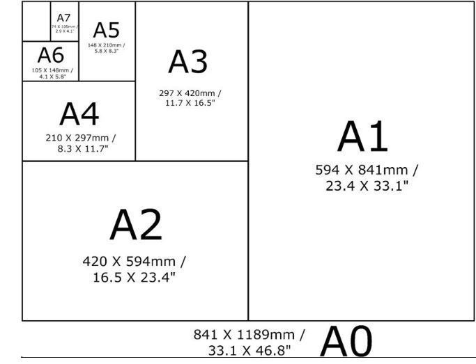
As it can be seen, the resolution wasn’t that great, and the size wasn’t exactly right either. I wanted an A2 size poster, so that would require some changes on the selected picture. A2 size is depicted below.
So, I edited the picture on Photoshop to the A2 measure (in mm) and a resolution of 150 dpi (normally, enough for picture printing). Of course when you increase the picture size, quality is going to get decreased – and that’s why it is so important to get the original picture in the highest resolution you can. I also took the opportunity to crop out the parts in the picture I didn’t want. I also added a 30 mm bleeding frame to it, so it would have some white spacing between the hard frame and the picture, after framed. The end result (here, in lower res) was like below:
Now, to print it, I opted for a print shop with online service. That is so much more convenient. I chose https://www.instantprint.co.uk/, created an account, picked the print size (A2) uploaded the jpeg and they generated the digital proof, all in real time. You then need to approove the proof and pay for it (it cost me 8 pounds). Two days later, it arrived. Meanwhile, I bought the frame at Amazon, for about 12 pounds, which arrived 24hs later.
The final result can be seen in the below picture.Total cost: 20 pounds (I guess it could be cheaper if you can get it printed for less and make your own frame…!).
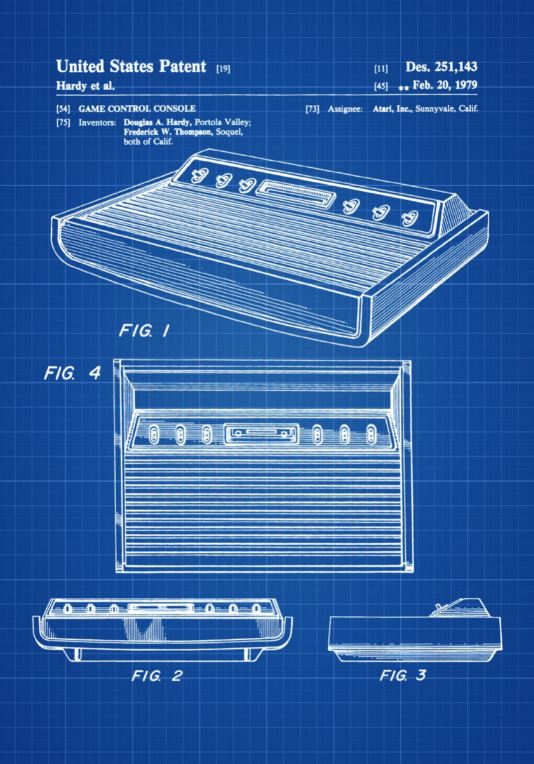
The result was so great that I am working on an A1 size poster, now. This one would use the Atari patent picture I found on the Net (below). Hopefully, it will turn out as nice as the Penguin one! I will tell you all about it later, when it is ready.
This video shows a full disassembly of a Powerbook 3400c, thorough cleaning and test. This Powerbook was bought at eBay for 40 quid, in an operational state. But the PRAM (CMOS) battery needed to be removed to avoid leakage, so I took the opportunity to fully disassemble it and clean it.
In this post I elaborate a bit more on the issue itself, and also give you some tips on how to figure out where is the defective potentiometer (pot) that is causing the issue. It could be a linear (slider) pot or a rotary (knob) pot. In my case, it was a knob pot (the AMP knob).
The ghost editing issue is a well known and common issue on the Roland JP8000 synths. Apparently, Roland tried to save up on components and didn’t use high quality pots in this particular synth, which results in some of them failing after almost 20 years.
The linear pots (the sliders) are easier to clean and lubricate, as they have a slot where the service can be done. Ideally, if the condition of the pot is way to bad, you should desolder it, disassemble and clean each component individually. But most of the time, a good cleaning with compressed air, isopropyl alcohol (99.9%) and a good fader lube (like Deoxit) does the job.
The rotary pots (knobs) are a bit trickier. Problem is that there is no good access to them. They are tightly closed and no cleaning can be done on them. I tried spraying some Deoxit on them, and it does get it. You can tell by the way they rotate after Deoxit has been sprayed. But in my case, the defective knob did not improve its condition after the “cleaning”. The video below shows my test after the cleaning. The issue remained.
Tip: To figure out which pot is generating random values at will, press and hold the SHIFT button. If any value is changed on ANY pot, you will see that in the LCD display. This is also an easy way to test some pots and see if the values they generate upon activity seem correct. The video shows this technique.
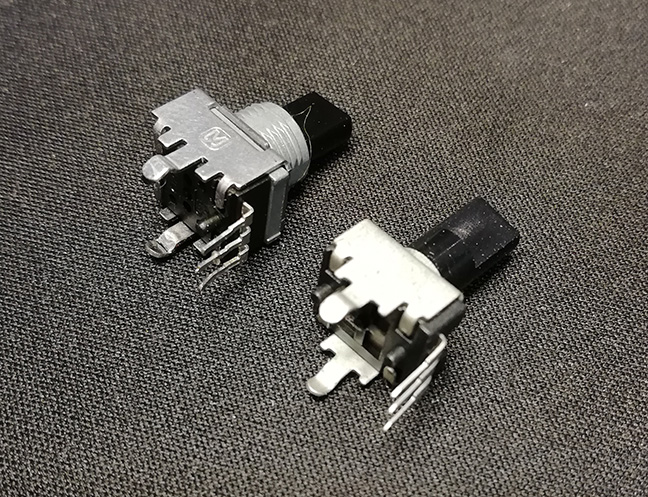
So, I had to desolder the pot and replace it. Luckily, finding replacement rotary knobs for the JP8000 is not that hard – and they are relatively cheap too. So, I went to eBay and bought 12 of those, 6 without center indent and 6 with it. Spent a total of 20 quid on them. Not too bad. They are not exactly the same, but they fit perfectly. The picture below shows on the left the original (defective) pot, and on the right, the replacement one. Case anyone is interested, they were bought from the user “synth-shack” at eBay.
So, pot replaced and new test done. Result: 100% OK this time 🙂 I also took the opportunity I was going to fully disassemble everything once again to replace the LCD display with a OLED one. Found a guy selling this at eBay for 50 quid and took a chance. The result can be seen in the below video.
So, there you have it…! A very nice vintage synth, with a lot of history to it, fully repaired and cleaned, and added to my collection. I am very pleased with the results!
I bought this JP8K at eBay last week for a fair price. Condition looks OK – not too beaten up – but it requires some work – as with all synths with this age.
The JP8K is a 20 years-old “virtual analog” synth. It was release in 1997 and it was the first of its kind to offer a special oscillator named “supersaw”, which combined multiple saw oscilators into a single one, allowing the creation of amazing “new” sounds. Because of that, this synth was extensively used in trance – and electronic – music in general – until today.
To take this synth apart, a lot of work is required. It is not a straight forward procedure. For this first part, I will leave you with the quick video I made about the issues and you can also see the overall condition of the synth. It is dusty, a bit marked and it also came with one slider cap missing. In the next post I will share everything I’ve done to clean it up and repair it (hopefully) and, finally, post a video with it fully working as new.
Existem hoje no mercado vários computadores baseados em FPGAs que emulam com bastante fidelidade computadores e consoles antigos. Para quem não sabe, FPGA (Field Programmable Gate Arrays) são chips que podem ser facilmente programados para realizar quase qualquer tipo de tarefa. Para isso, eles precisam de um conjunto de instruções para lhes dizer o que fazer. O interessante é que o mesmo chip FPGA pode realizar tarefas completamente distintas, bastando que seja instruído para tal. Assim, sabendo como fazer, é possível escrever instruções para que um FPGA assuma 100% das funções de um processador Z80, por exemplo. Não apenas isso, mas havendo espaço, é possível também sintetizar outros chips no FPGA, por exemplo, memória, chips de áudio, etc. Resumindo, se o FPGA for robusto o suficiente, é possivel replicar todos os chips e funções de um computador. Em um único chip.
Este foi o conceito adotado pelo OneChip MSX, criado em 2006. Basicamente, o sistema adota um FPGA para sintetizar todas as funções de um MSX 2+ – incluindo o chip de som SCC.
Em 2015, fascinado pelo conceito, eu comprei o MiST por cerca de 180 libras. Apesar de um computador FPGA não substituir a experiência de se usar o hardware original, no quesito fidelidade, ele chega bem perto. O MiST, assim como o OneChip MSX, usa um FPGA para sintetizar plataformas completas. A diferença aqui é que, enquanto o OneChip MSX é instruído para apenas sintetizar a plataforma MSX, o MiST é capaz de sintetizar muitas outras. Amiga, MSX, Atari, Apple II, Commodore 64, NES e muitas outras são possíveis! Atualmente, existem outros projetos que fazem o mesmo que o MiST e até mais. Uma delas é o MiSTER.
Quer ver o MiST funcionando? Eu fiz um pequeno vídeo em 2015 sobre ele, assim que ele chegou para mim. O vídeo mostra como carregar as plataformas no FPGA e também um pouco do que é possível ser feito. Segue abaixo.
O MSX Expert foi o computador que eu mais aproveitei e gostei quando tinha meus 15 anos de idade. O Expert me abriu as portas para o mundo da tecnologia, programação, jogos, aplicativos e utilitários e acesso remoto. Infelizmente, ele queimou e acabou sendo substituído, depois, por um PC.
Anos e anos mais tarde, a saudade bateu. Pensei “Por que não comprar um Expert usado para curtir um pouco as pérolas daquela época?”
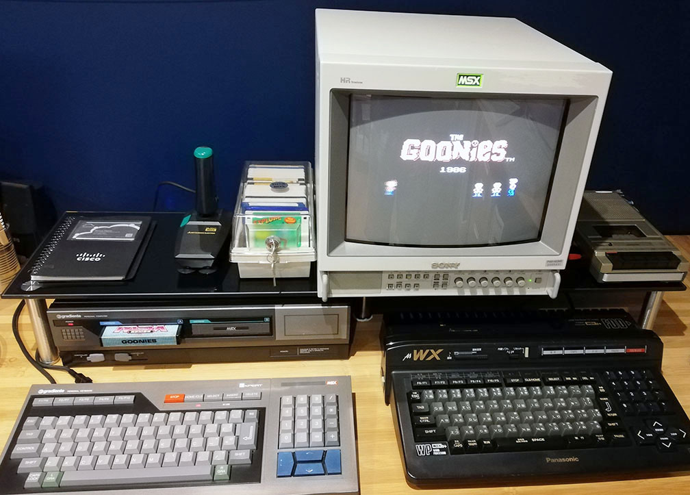
Alguns vão dizer que é bobagem comprar uma máquina com mais de 3 décadas de idade, se um emulador pode rodar todos os softwares daquela época com perfeição. Não apenas isso, mas os emuladores podem incorporar qualquer MSX: 1, 2, 2+ e até mesmo o Turbo-R. Emuladores são mesmo muito legais, mas a experiência de ter o hardware original em mãos é indescritível. Assim sendo, optei por comprar um MSX Expert original (sem modificação para 2.0 ou qualquer outra) no Mercado Livre. Demorei para achar um em bom estado, mas consegui um Expert 1.1 funcionando, cosmeticamente decente e com todos os manuais e acessórios originais. Veio também com o cartucho “Ligue-se ao Expert”! Isso foi há uns 4 anos e, pelo que me lembro, paguei cerca de R$ 400 nele. Pelo estado e pelo que veio junto, achei o preço justo.
O primeiro monitor que usei no meu “novo” Expert foi um lendário Commodore 1084s (um monitor de tubo CRT, para quem não conhece). Fiz o cabo RGB seguindo algumas instrruções online e funcionou perfeitamente. Bom, quase perfeitamente… reparei que a imagem ficava trêmula. Bem pouco, mas ficava. Percebi que se eu mudasse o monitor de lugar (colocando ele ao lado da CPU em vez de em cima), a imagem estabilizava um pouco. Mais adiante, comprei um monitor Sony PVM 1453MD, e percebi que o problema com a imagem se repetia. Fiz um teste com o PVM ligando outro MSX na linha 2 RGB dele, e percebi que a imagem do outro MSX também era afetada se o Expert estivesse ligado – mesmo se a conexão RGB dele com o monitor fosse desfeita. Após este teste, não tive mais dúvida: A fonte do Expert estava causando algum tipo de interferência. Eu teria que trocá-la. Minha idéia original era arrumar um traffo compatível e apenas substituir o antigo. Mas percebi que ninguém fazia isso. O pessoal estava trocando a fonte do Expert por uma fonte chaveada de PC (tem um artigo na MSXPro que descreve em detalhes como proceder). Achei que fazendo isso, meus problemas com a imagem seriam resolvidos. Cheguei a comprar uma fonte de PC para desmontá-la e fazer a troca no meu Expert, mas num belo dia, pesquisando pela internet, caí num artigo no blog Retropix que descrevia o processo de adicionar uma fonte externa no Expert. A princípio, não fiquei muito seduzido pela idéia, mas lendo o artigo até o fim, me deparei com o seguinte:
[…] quando havia uma fonte ATX dentro do gabinete, a imagem ficava meio que flutuando, quando ligava o micro. Eu já tinha colocado umas 2 fontes ATX diferentes e o resultado era o mesmo, parecia uma interferência com o video. Agora com a fonte externa isso acabou, a imagem ficou fixa, perfeita nesse sentido.
Ou seja, provavelmente, se eu adicionasse a fonte chaveada ao meu Expert, o problema com a imagem continuaria… foi uma sorte eu ter me deparado com este artigo! Decidi, entáo, tentar a solução proposta pelo blog Retropix. Finalizei a alteração hoje, e posso escrever – com muito alívio – FUNCIONOU! Imagem 100% estável, finalmente! E a solução em si é mesmo muito mais prática e elegante! Se der problema com a fonte, basta comprar outra e plugar no Expert, sem necessidade de abrí-lo.
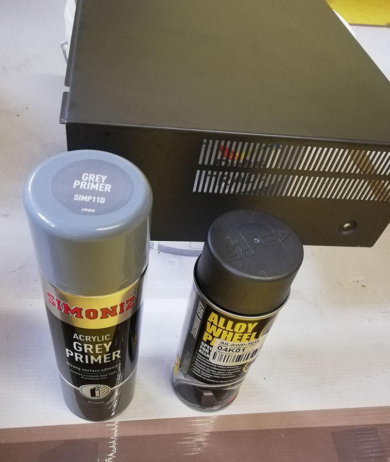
Aproveitei que teria que desmontá-lo inteiro para pintar a cobertura. Por sorte eu tinha uma lata spray de primer e uma lata spray de tinta cinza metálica que bate quase que perfeitamente com a cor original do Expert. O resultado final, eu compartilho abaixo.
OBS: Para realizar esta modificação eu segui à risca o tutorial do site MSXPro (pois é necessário modificar a placa analógica do Expert), e as instruções postadas pelo blog Retropix. Eu utilizei exatamente o mesmo componente que ele descreve, adquirido no ebay aqui na Inglaterra, por 12 libras. Obviamente não me responsabilizo por quaisquer problemas!
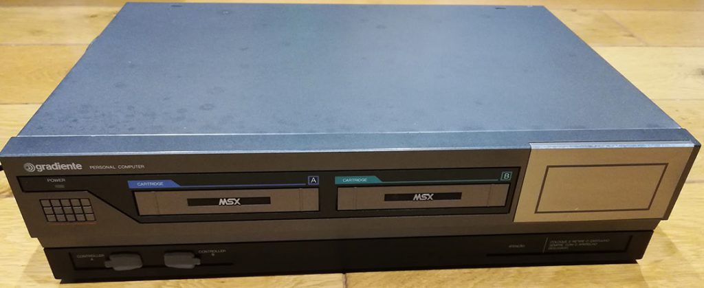
Antes de começar, achei legal tirar uma foto do velho Expert, antes da empreitada. Ei-lo:
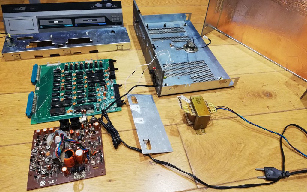
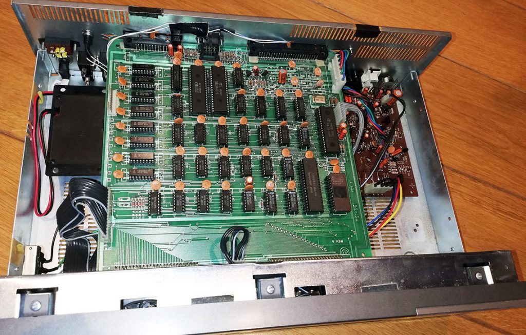
Tudo desmontado já com o traffo removido:
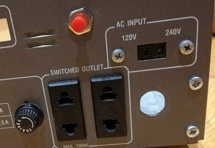
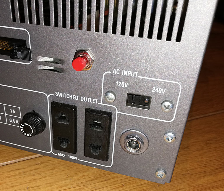
Cabo de força removido – a idéia foi utilizar a mesma abertura para o conector da fonte externa. Mantive as tomadas, fusível e chave seletora de voltagem apenas por razões estéticas. O botão vermelho é um botão reset que instalei em outra ocasião.
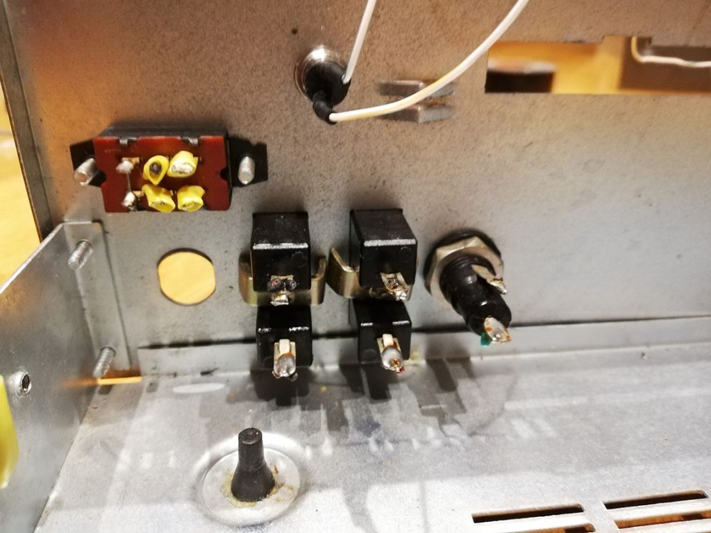
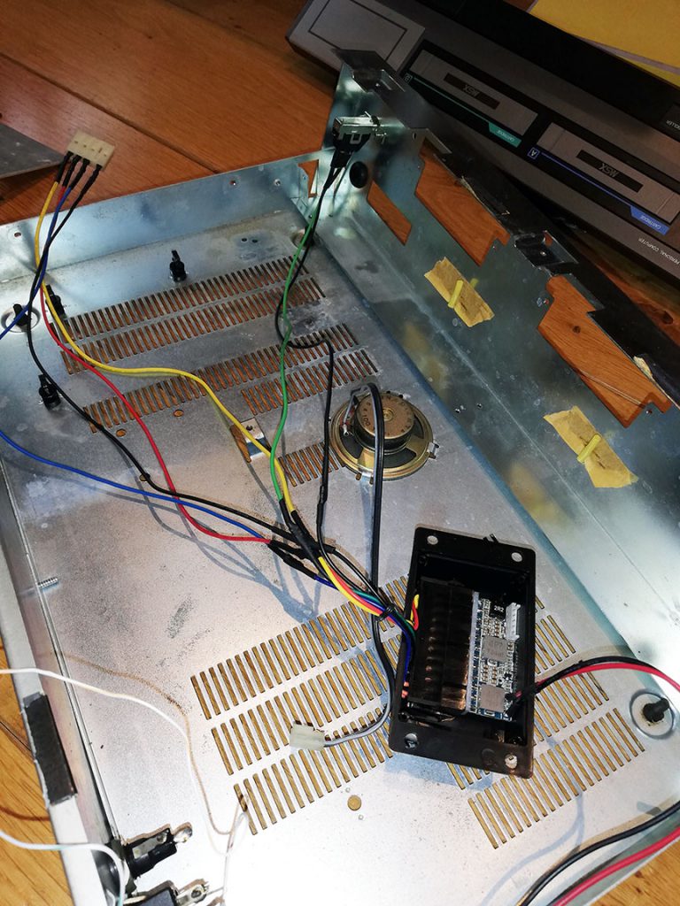
Retirada de todos os cabos elétricos internos. Afinal, eles não serão mais necessários.
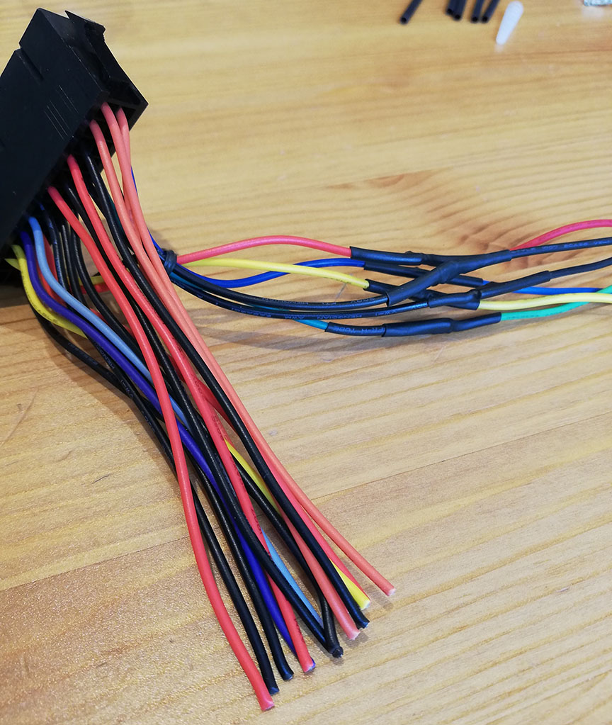
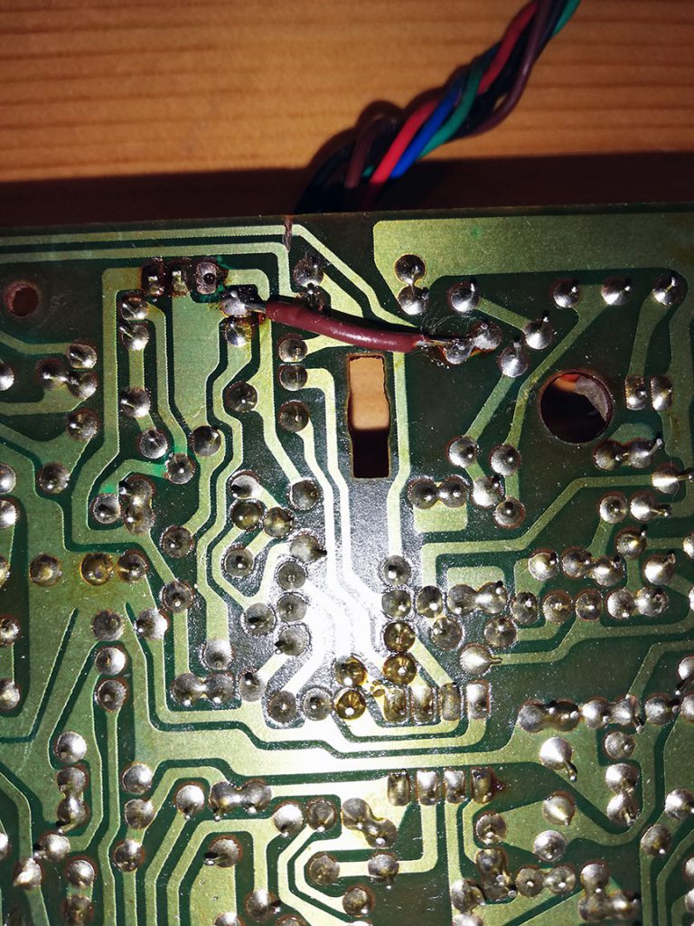
Preparo do cabo que vai ser conectado à nova micro fonte. Apenas os 6 fios à direita serão utilizados. Todos os outros serão, posteriormente, cortados.
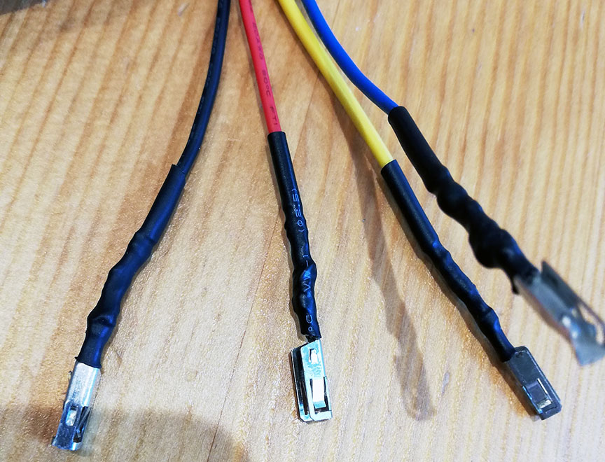
Solda e acabamento dos pinos que serão conectados à placa lógica do Expert:
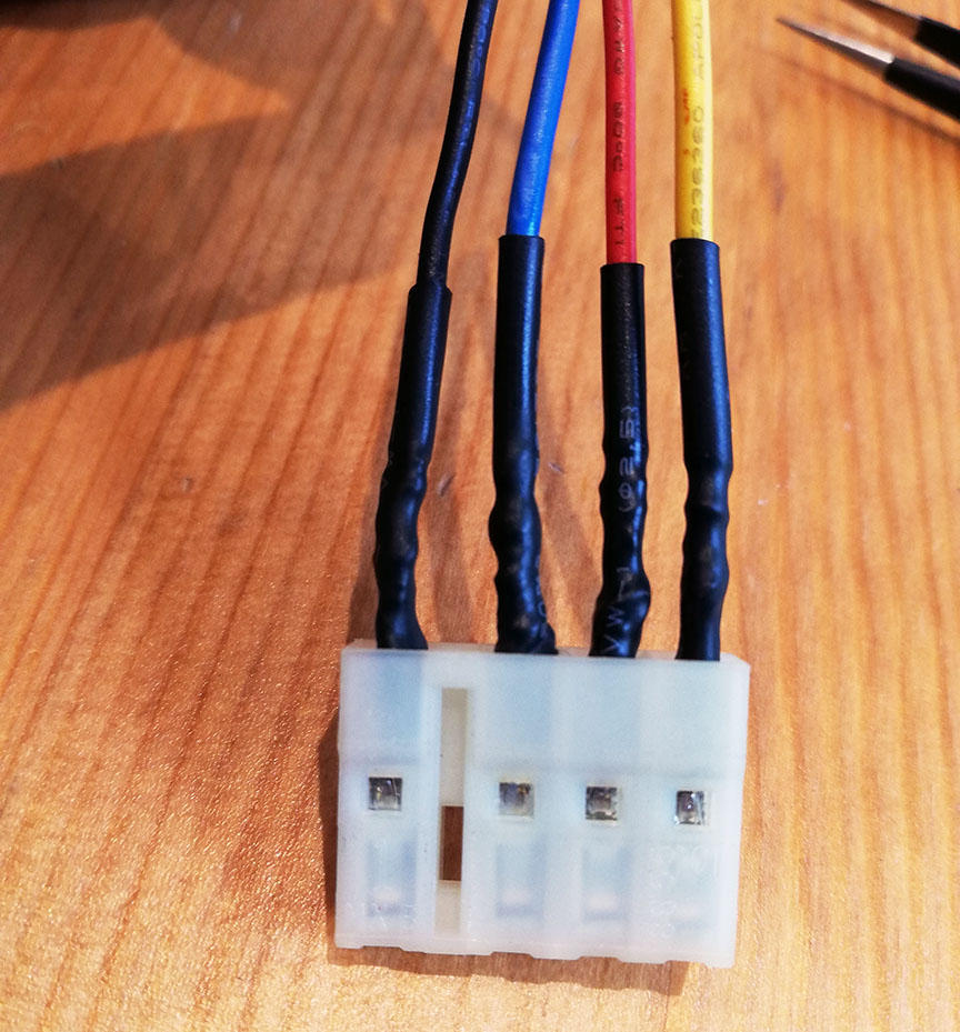
Montagem do conector:
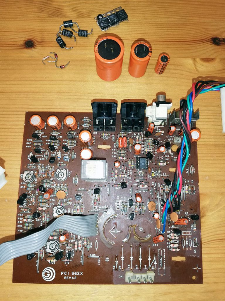
Remoção dos componentes e alteração da placa analógica:
Montagem da fonte Pico ATX – utilizei uma caixa plástica similar à usada no site Retropix, para evitar o contato da fonte com o chassis do Expert:
Aqui, com a tampa da caixa plástica fechada:
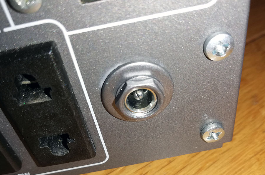
Eis o conector instalado onde antes passava o cabo de força:
Por outro ângulo. Ficou bem harmonizado!
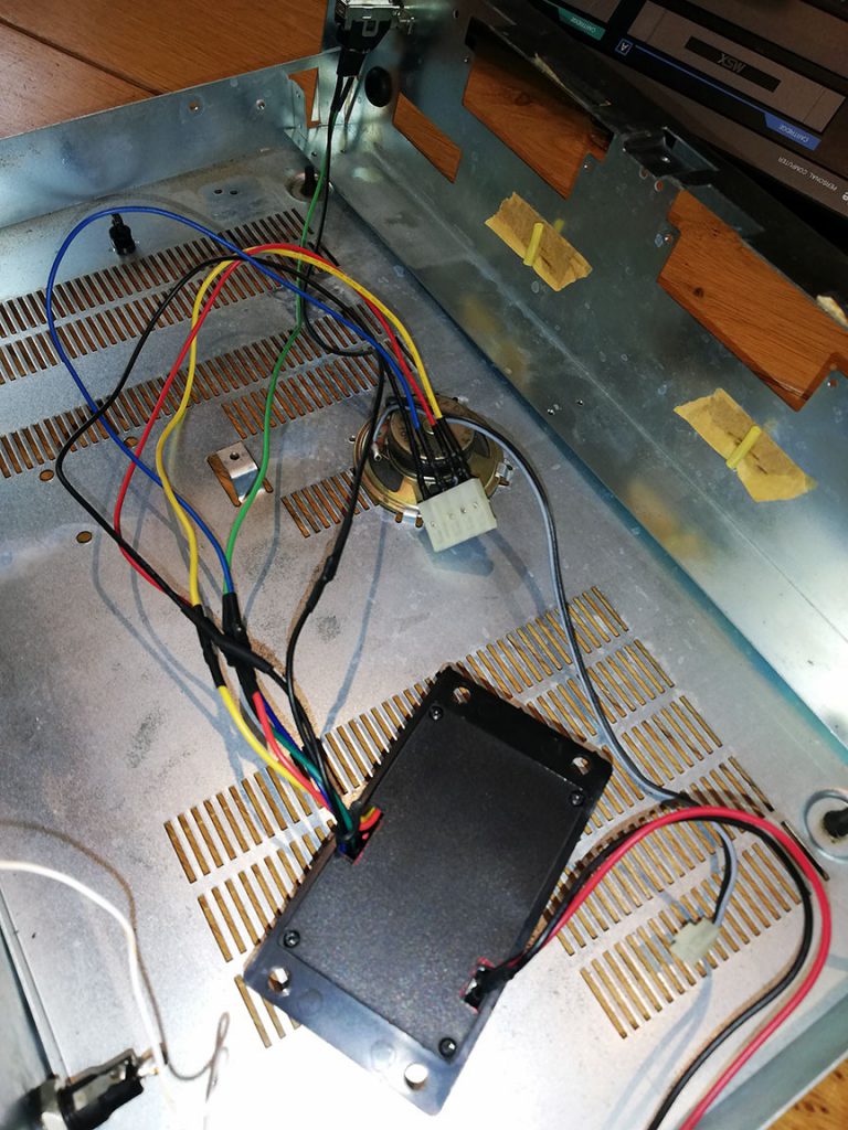
Tudo montado com a nova fonte (ainda sem testar). A caixa plástica foi fixada com cola quente ao chassis do Expert. É possível abri-la sem descolar a caixa, caso seja necessário. Basta desparafusar a tampa. Observe o espaço no lado direito, sem o traffo original e o dissipador de calor.
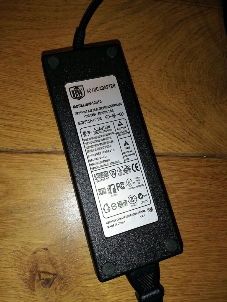
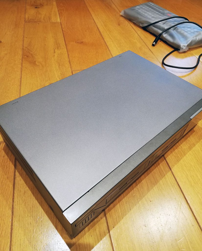
Esta foi a fonte que comprei. A fonte tem saída de 12v e 10A, mais que suficiente para aguentar o tranco.
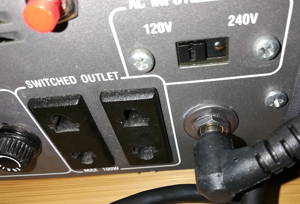
Fonte conectada ao Expert:
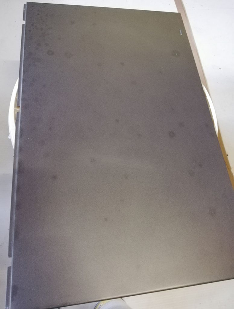
Hora de cuidar da pintura da cobertura original. Pela foto abaixo, percebe-se o estado dela… várias manchas na pintura causadas pela idade avançada do micrinho.
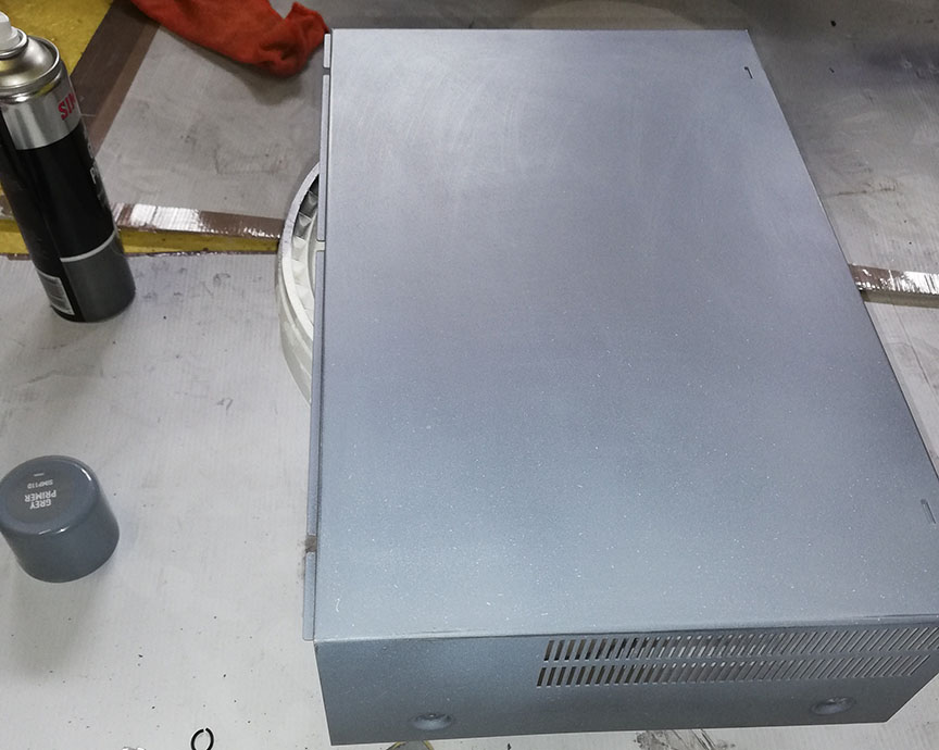
Preparo da cobertura para a pintura: Várias camadas de primer, uma boa lixada e várias camadas de tinta.
Primer, lixa, primer, lixa.
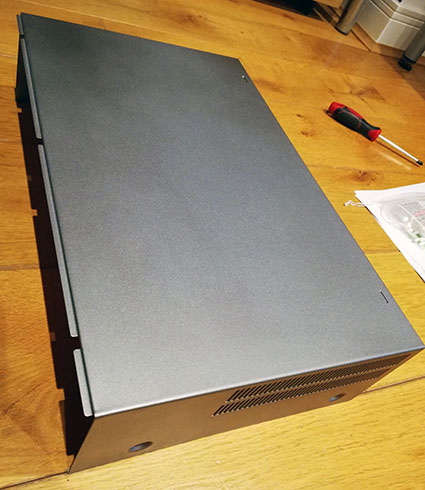
Resultado final da pintura. A cor é quase igual à original.
Expert fechado, montado e pronto para o teste final:
E, como eu já havia contado antes, funcionou! E, SIM, resolveu o problema da imagem. Está 100% estável! Obrigado Retropix pelas dicas!!!
Em breve publicarei mais posts sobre minhas aventuras no retro-mundo! Até a próxima!
For while I wanted a home office that suited my needs. I collect some old (and heavy) computers and a big and solid bench was a major requirement. I also needed a space to work (of course) and a space to play with my music (a big hobby of mine).
Being a “do-it-yourself’er”, I decided to set a budget, design and build the whole thing myself. I thought it would become a fun side project – and it sure did!
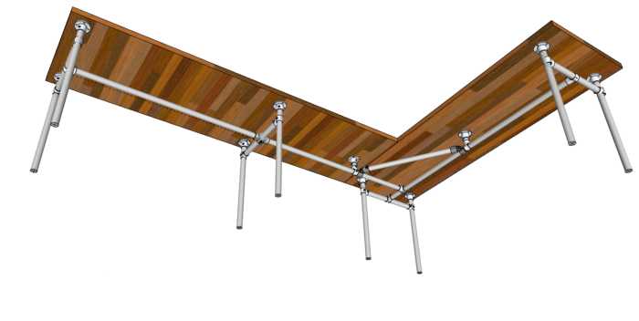
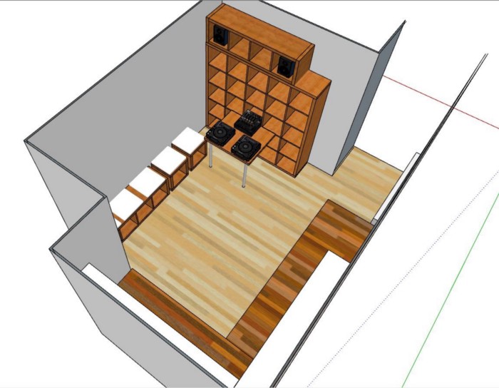
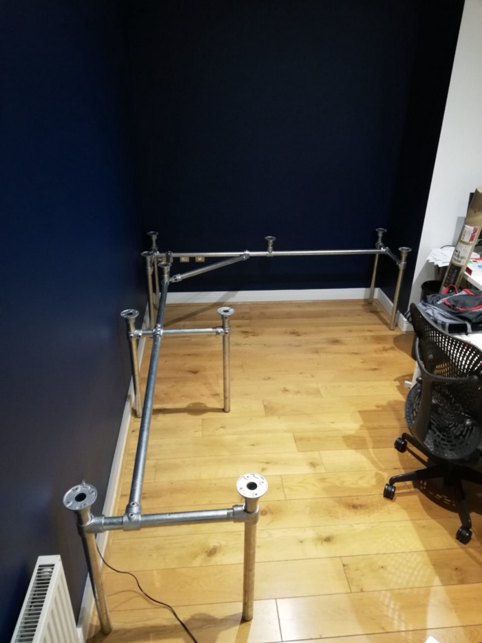
To get things right, it was mandatory to get all measurements and use some sort of 3D tool to design everything. I had never used 3D design tools before, so I went on to Google for some tips. In the end, I decided to give SketchUp a shot. Watched some YouTube videos to learn how to use the tool, and on I went. The first thing was to create the massive L shaped desk. The desk measured 2.5 m x 2 m with a 85 cm depth. Plan was to use kitchen worktops made from solid wood, 5 cm thick. So, the base needed to be VERY strong. Another requirement I set was to have enough free room for my legs all around the table (specially in the corner). So, I decided to use industrial strength galvanised pipes for that. It would also be easier to put together and to order the parts exactly as I wanted them. After several trial and errors, the desk 3D project looked pretty much the way I wanted:
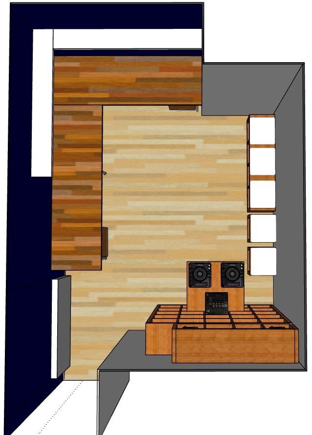
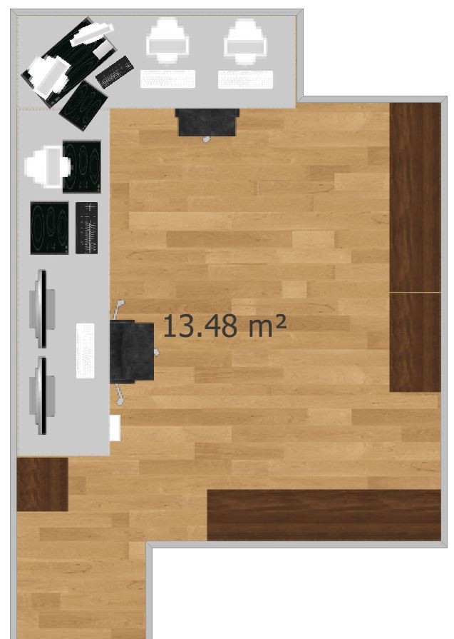
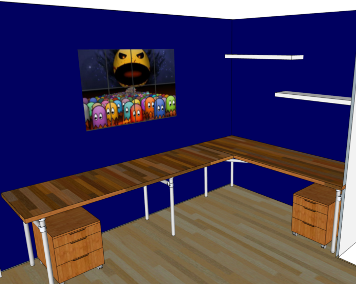
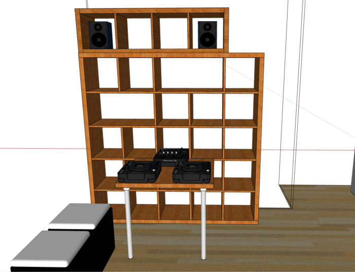
Next, I added the shelves and drawer units (all from IKEA, which made me stick to the defined budget). This is the top view:
And a different angle view:
How I planned to lay everything out in the available space:
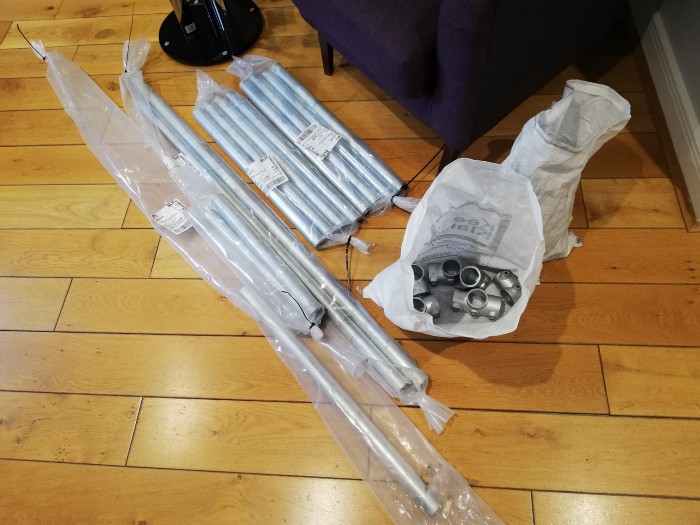
When the parts started to arrive, I realized that putting everything together without any help would be very tricky. I should have lost about 6 pounds with the workout 🙂
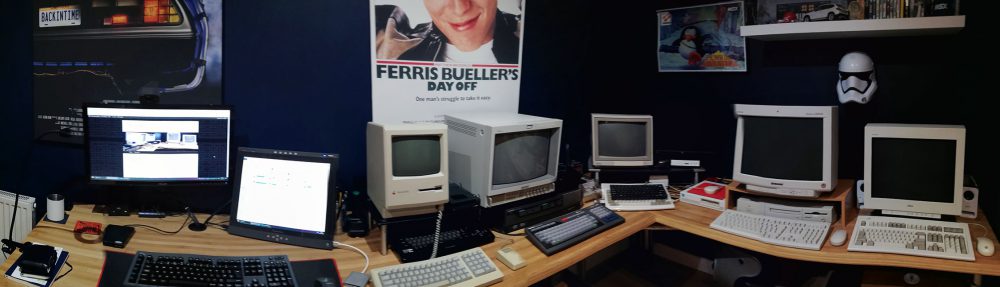
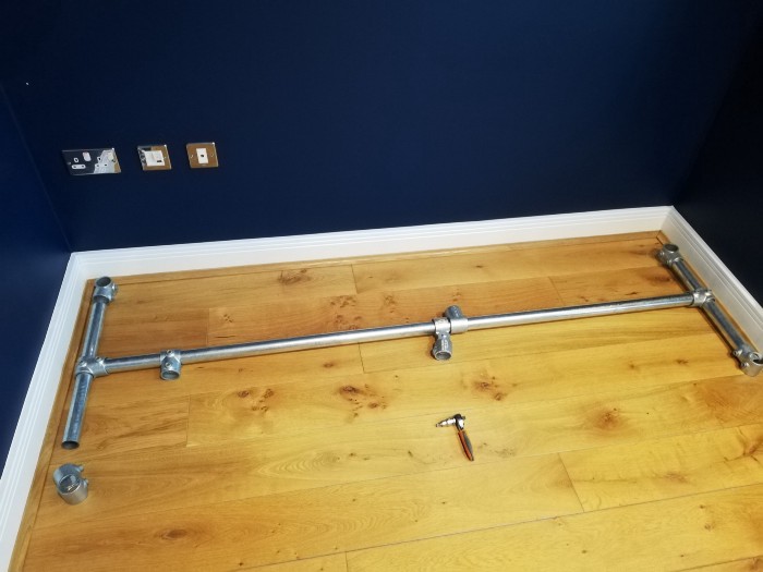
How nice it is to see things going exactly as planned!
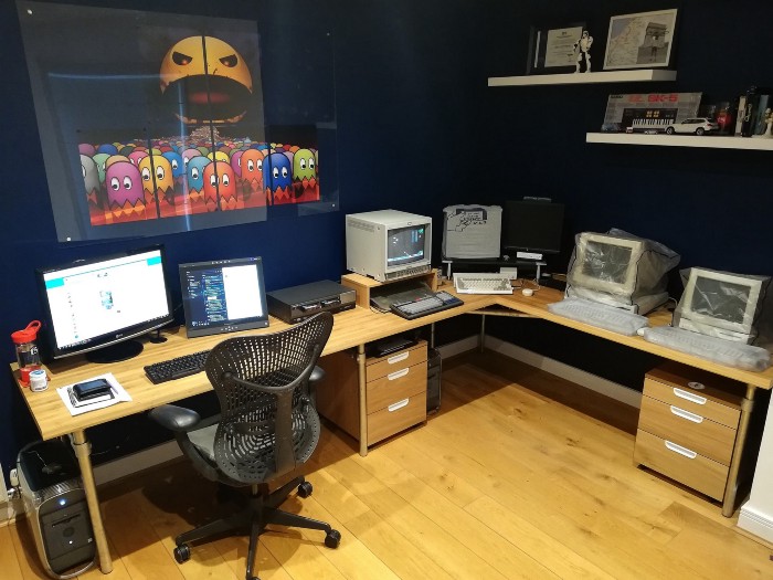
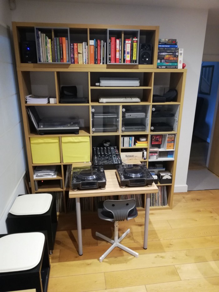
Finally, after 3 weekends of very hard work, the project was concluded with great success. So, I present here the end result, comparing the projected and the actual result:
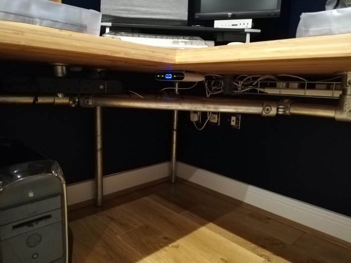
And the cables… well… they are all tucked in under the desk:
I have to say I am proud of myself for being able to pull this off… I am a tech guy, afterwards! Not a builder or an interior designer! And, from what I quoted, doing the project myself costed less than half than if I had hired a contractor / interior designer. And, well, I really loved the result!
Case anyone is interested, here are the suppliers for everything I used:
Worktops for the desk: worktop-express.co.uk
Desk base (galvanised pipes): simplifiedbuilding.co.uk
Shelf units and drawers: IKEA
3D software: www.sketchup.com (30 days free trial)